PLL based ULA
PLL based ULA
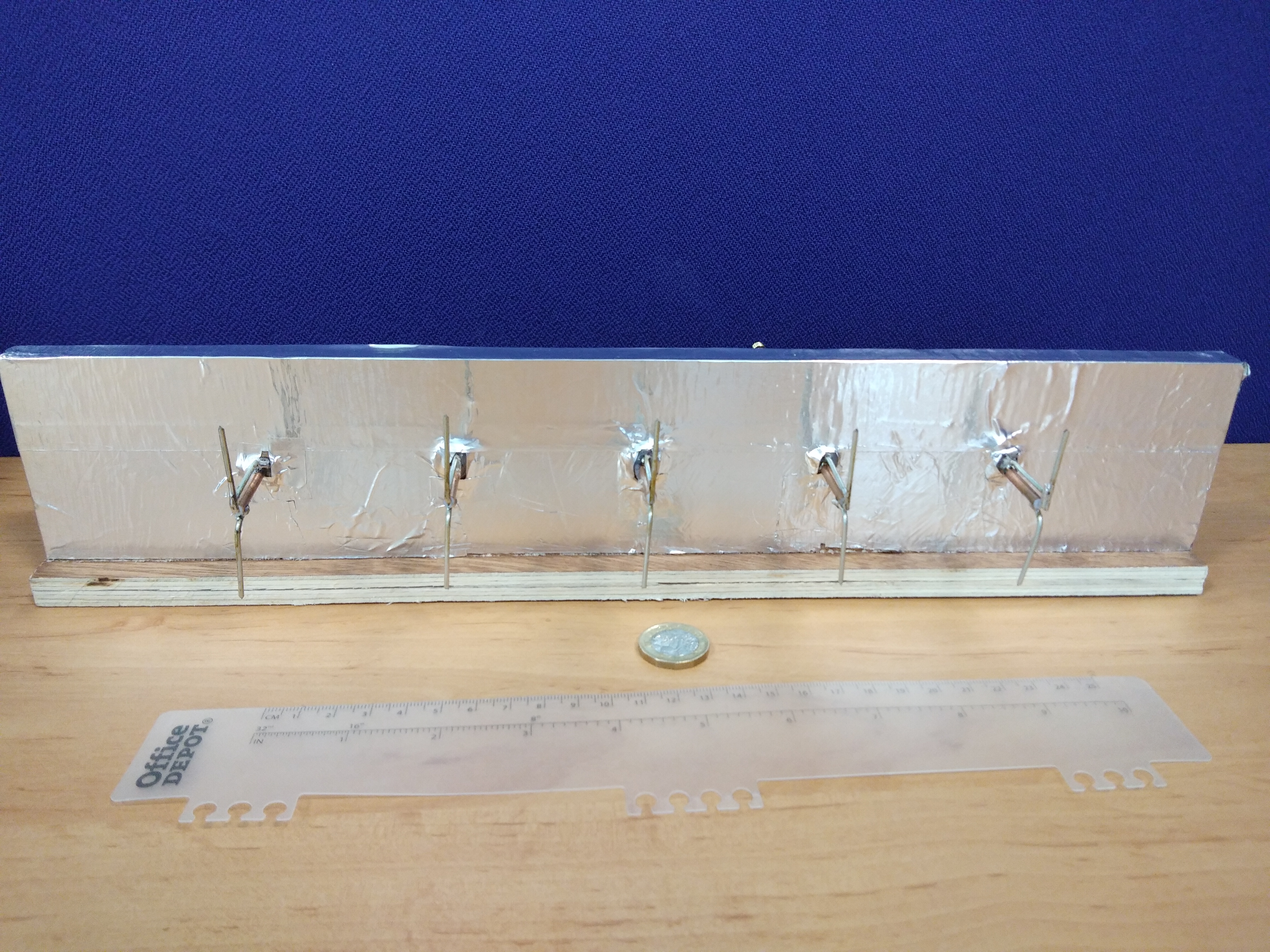
Hardware
The software application communicates with the microcontrollers via a serial interface over RS-485. For this two PCBs have been made.
The first PCB was designed to connect to a spark fun FTDI breakout board
This board contains an MAX3089 RS-485 transceiver and connectors to a RJ-45 socket allowing a standard ethernet LAN cable to be used to connect between the PLL array and PC
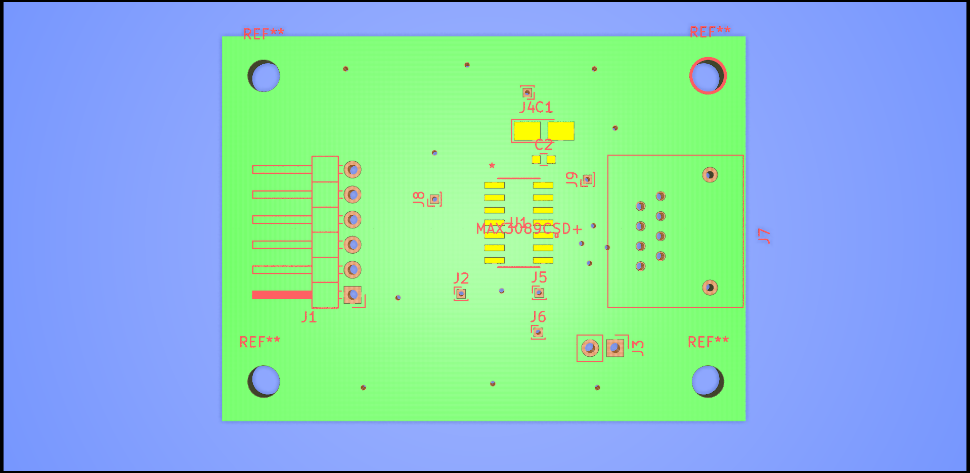
The PCB was designed in KiCAD and is available here.
A pdf of the schematic for the RS-485 to FTDI board can be found here
For the PLL side the rRS-485 signals run in a bus along the reference input side of the boards. With stubs going to a transceiver for each microcontroller. At each side of the board there is a 2x6 0.1” header which is connected to two pairs of differential signals and ground. The second board in a an interface between RJ-45 and this header
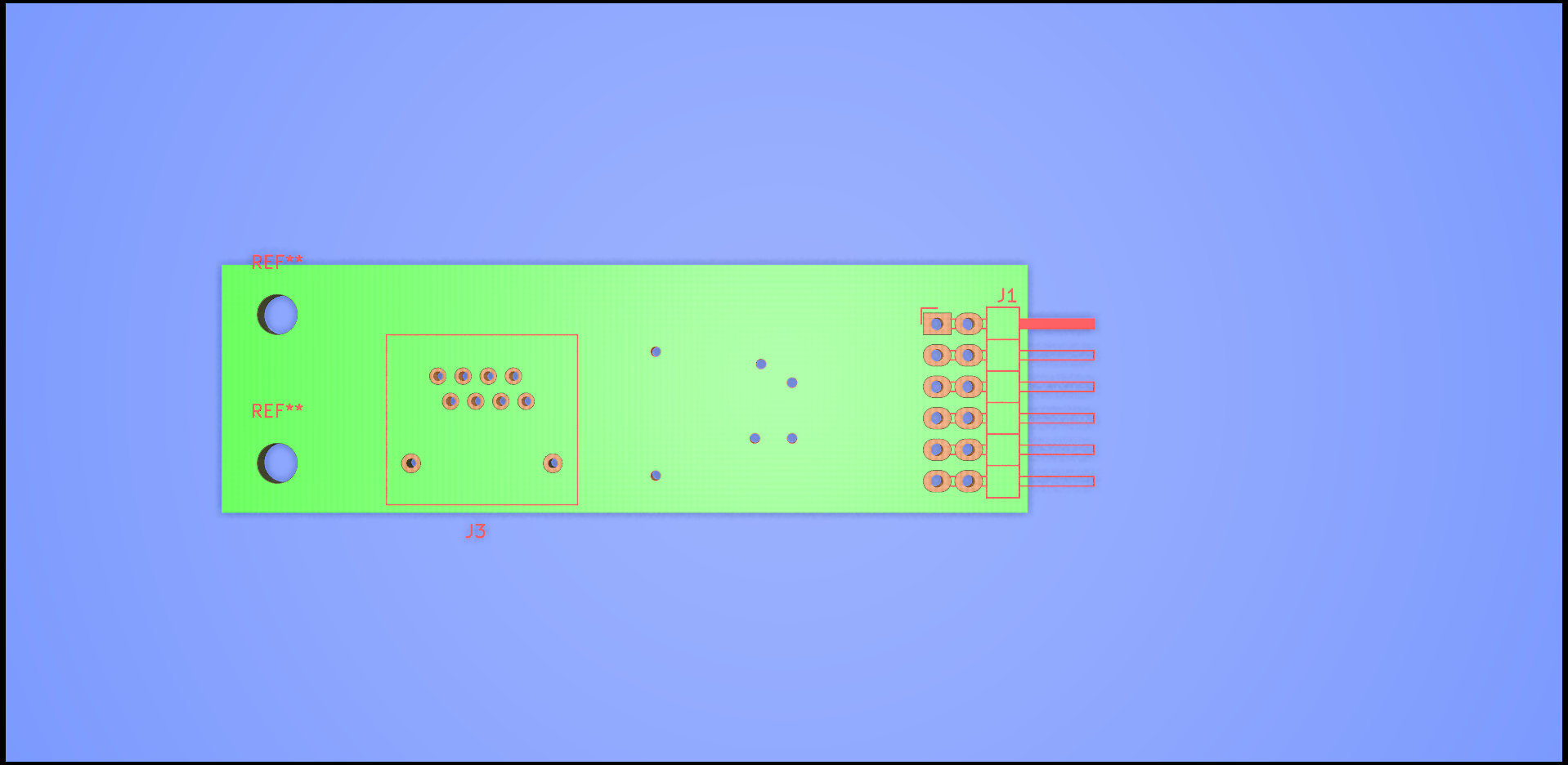
The PCB was designed in KiCAD and is available here.
A pdf of the schematic for the RS-485 to FTDI board can be found here